|
|
|
|
Home
Products
Web
Store
Product
Customization
OEM/ODM
Contact |
|
|
|
|
|
|
|
Function Description |
X725
|
|
|
|
|
|
|
|
 |
|
|
|
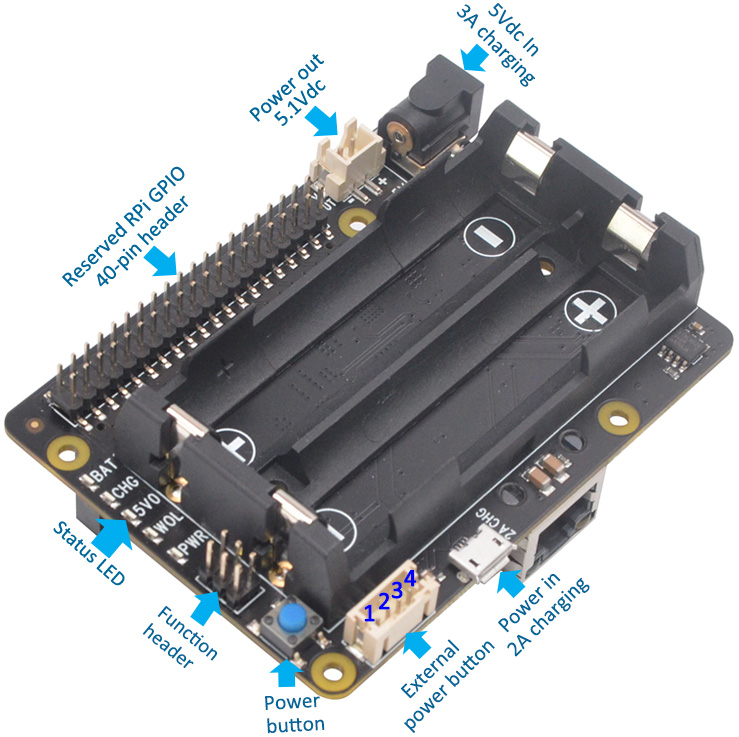
| ❶ |
Power Jack and
Connector |
|
|
|
|
Power input |
5Vdc +/- 5% , 2.5~4A |
|
DC Power Plug Size |
5.5*2.5mm |
|
Micro USB power socket |
Pin 1 - 5Vdc, Pin 5 - GND |
|
UPS power output |
5.1Vdc
8A |
|
Power output connector |
XH2.54mm 2pin |
1. X725 powers the
Raspberry Pi via the 40-pin header (Pin 2 & 4)
2. Don't power the Raspberry Pi via the Pi's Micro USB socket
3. X725 can be powered via the onboard DC jack
or
Micro USB
power socket |
|
|
Jumper Name |
Usage |
|
Auto ON |
Short
- Auto power-on when power applied |
| Open
-
Power on when power button pressed |
|
AUTO SD |
Short
- Automatic shutdown enabled when
battery
low (3Vdc ) |
| Open
- Short - Automatic shutdown disabled |
|
Lan PWR |
Short
- Ethernet powered by battery when power
adapter
not connected |
Open
- Ethernet disabled when powered by
battery
*Save power and extend battery life |
|
|
|
|
|
|
❸ |
Connector for
External Power Switch |
|
|
|
|
Pin No. |
Pin Description |
|
1 |
Power on/off control connecting to switch |
|
2 |
Ground |
|
3 |
LED+
for battery low indicator |
|
4 |
LED+
for power on, rebooting and shutdown |
1. Please use
momentary switch only and not use latching switch
2. Connector - Pitch 2.0mm 4pos |
|
|
Press and Release |
Raspberry
Pi and X725 turn on |
|
Press and hold for 1~2 seconds |
System
rebooting |
|
Press and hold for 3~7 seconds |
System shutting down |
|
Press and hold for >8 seconds |
Force
shutdown |
|
|
|
|
|
|
|
|
|
❻ |
18650 battery dimension |
|
|
LED Name |
Usage |
|
BAT |
LED
red blinking when battery low (≤3.0Vdc) |
|
CHG |
LED
red on indicates battery charging
LED off indicates battery is fully charged |
|
5V0 |
LED green on indicates 5V power out |
|
WOL |
LED
green on indicates power on/wake on LAN |
|
PWR |
LED
blue indicates
Stays on - Power on
Blinks rapidly - system rebooting
Blinks slowly - Shutting down |
|
|
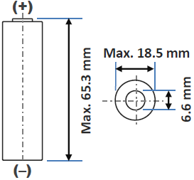
DO NOT USE 18650 BATTERY
WITH BUILT-IN PROTECTION CIRCUIT |
|
|
|
|
|
Pin No. |
Usage |
|
2, 4 |
+5V
power supply |
|
3, 5 |
I2C for
UPS battery voltage & percentage reading |
|
6 |
Ground |
|
7 |
GPIO4
for power management |
|
11 |
GPIO17
for power management |
|
12 |
GPIO18
for power management |
|
|
|
|
|
|
|
|
|
|
|
Board Assembly |
|
|
|
|
|
|
|
|
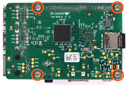
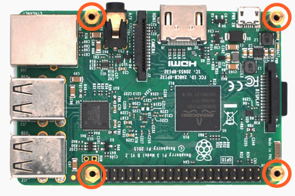
❶ |
Push a screws
(M2.5*6mm) up through
the mounting hole on the underside of the Raspberry
Pi. |
|
|
|
❷ |
Screw the spacer (M2.5*23mm)
down until it is hand tight |
|
 |
|
 |
| |
|
|
|
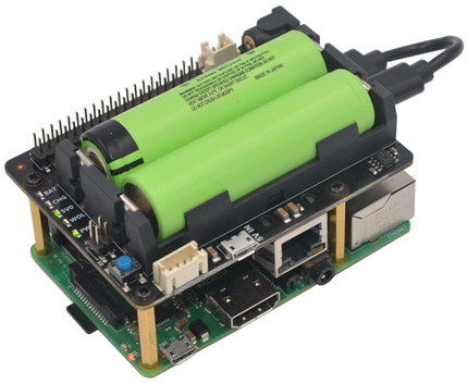
❸ |
Plugs the X720 board
straight into your Raspberry Pi B+'s GPIO header and
screw down
(M2.5*6mm) |
|
|
|
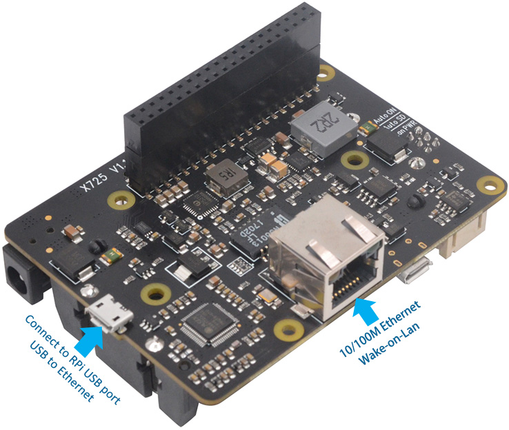
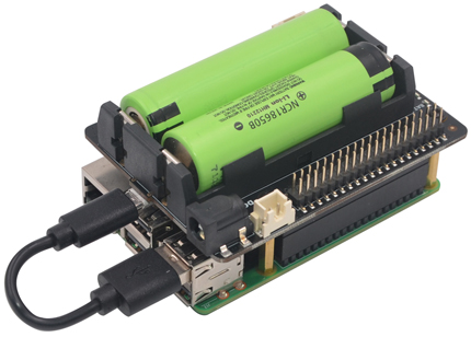
❹ |
Optional -If need 2nd
Ethernet and WOL function, connect X720 to Raspberry Pi with
the USB to Micro-USB Cable |
|
 |
|
 |
| |
|
|
|
|
|
|
Case Assembly |
|
|
|
|
|
|
|
|
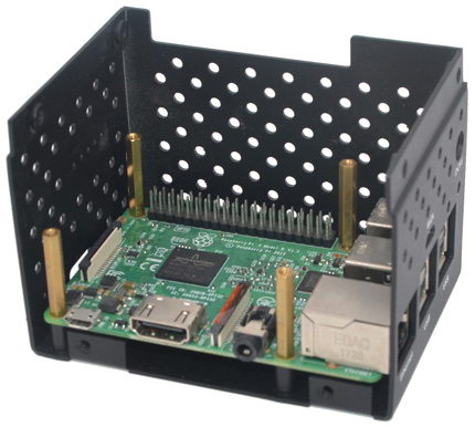
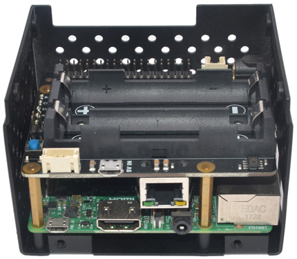
❶ |
Mount the Raspberry
Pi board onto the
bottom case and screw down
(M/F Hex standoff 23mm)
using a socket spanner |
 |
|
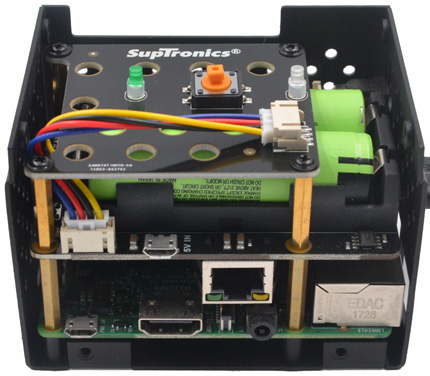
| ❷ |
a) Plugs the X720 board
straight into your Raspberry Pi B+'s
GPIO header
b) Double check polarity of
battery's connector before
placing 1860 batteries into the holder |
|
| |
|
|
|
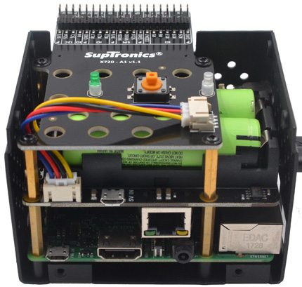
❸ |
a)
screw down X720 board (M/F
Hex standoff 21mm)
b) Connect the 4-pin cable from X720 to LED
& switch board
c) Place the LED & switch board and screw down
(M2.5*6mm) |
|
|
|
❹ |
Optional to install the GPIO reference board, repeat
step 3 |
|
 |
|
 |
| |
|
|
|
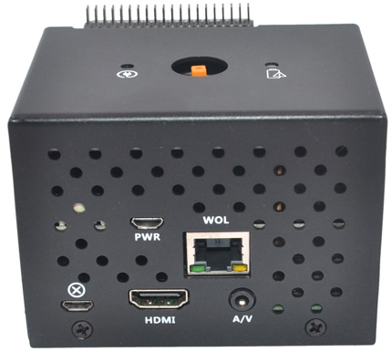
❺ |
Screw the top cover down
(M3*5mm) |
|
|
|
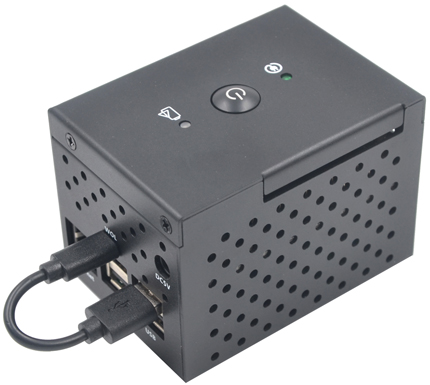
❻ |
a) Install the power switch cap
b) If need 2nd
Ethernet and WOL function, connect X720 to Raspberry Pi with
the USB to Micro-USB Cable |
|
|
|
 |
| |
|
|
|
|
|
|
|
|
|
|
|
|
|
|
© 2018
SUPTRONICS TECHNOLOGIES LIMITED, ALL RIGHTS RESEVERED |
|
|
|
|
|